Language:
Español
Reception:
QFH Antenna
Preamplifier
Original version
New receiver
Converter
Bandpass filter
Other information:
Links
Legend
Archive
Bibliography
Wallpapers
Where are we?
Pagers An extremely strong signal, just above the weather satellite band, blocked the TDA7000 and desensitized it noticeably. As these were pulse transmissions, random horizontal lineas appeared on the images.
OrbComm On alternating lines, very regularly, new interference lines appeared. The alternating lines suggested 1 Hz signals. Through the internet, I found out that this interference was due to a new satellite constellation, dedicated to vehicle communications, from a firm called OrbComm. For unfatomable reasons, their frequencies are distributed right in the middle of the satellite band.
According to some texts (excuses?), the frequencies were carefully selected to not interfere with the NOAAs, but, honestly, one would need a professional receiver to distinguish two signals so closely spaced. Who has a budget to buy such a receiver? And I'm not really talking about amateur reception only...
To promote security (I'm guessing here), the OrbComm satellites regularly change frequencies. The standard transmission is at a quite low baud rate, but there is also a satellite (also variable) which actually transmits at a high rate, continuously, and this produces interference over the entire width of the image.
|
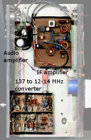
Audio amplifier: Inherited from the original receiver.
It's just a simple 5W amplifier with a TDA2002 amplifier and provides
ample audio level.
IF amplifier:
As usual, these modification projects initiate during the summer, when
component accesibility dwindles to a minimum due to the holidays.
The main problem was thus to make do with whatever came out of the
junk box.
Input converter: This converter takes the 137 MHz signal, amplifies it somewhat, and then mixes it with a crystal oscillator signal, down to 12 MHz. This converter is also an inheritance from the original receiver. |
| (c) John Coppens ON6JC/LW3HAZ |